Each analog input on your SCADAPack Modbus controller can be represented in your system by a SCADAPack Modbus analog point. The configuration of the point defines its alarm limit thresholds, formatting, historic settings, and so on.
Now you are going to create two analog input points which will represent two of the analog inputs on your SCADAPack Modbus controller:
- Display the Database Bar (see Display an Explorer Bar in the ClearSCADA Guide to ViewX and WebX Clients).
- In the Database Bar, right click on the ‘Site’ Group to display its context sensitive menu, and then select Create New>Modbus - Advanced>SCADAPack Modbus> Analog Input Point.
A new analog input point is created.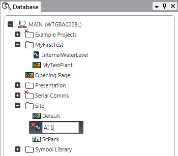
- Name the analog input point:
AI 1
- Display the configuration Form for the 'AI 1' point.
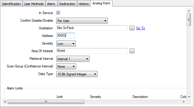
- Select the Analog Point tab.
- Select the In Service check box to enable the point.
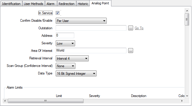
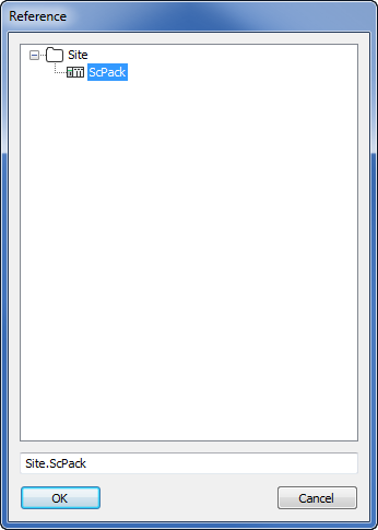
- Use the browse button feature of the Outstation field to associate the point with the 'ScPack' Outstation that you have already created.
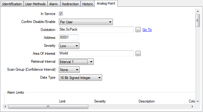
- Set the Address to 30001 (this is the first analog input on your controller).
- Set the Retrieval Interval to Interval 1. This sets the analog input point to be scanned at the rate defined for Interval 1, which is configured on the Form for the outstation (in this case, the 'ScPack' outstation has the default setting of 0.1 second for Interval 1).
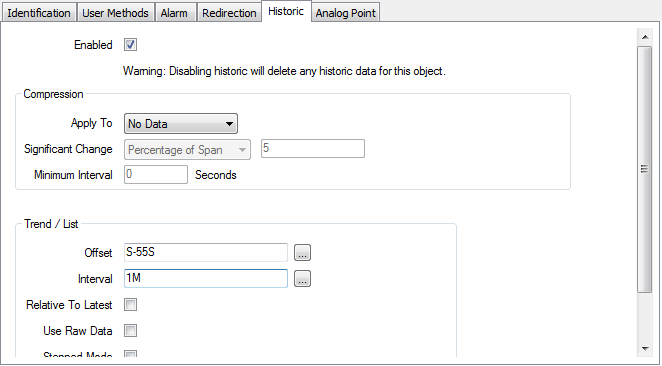
- Select the Historic tab.
- Select the Enabled box to activate the historic feature for the point. Your system will now store a record of the point’s values.
- Set the Offset to:
S-55SThis time setting represents the current second minus 55 seconds.
- Set the Interval to:
1MThis sets the Interval to 1 minute. So the Historic Trend for the point will show 1 minute on the x-axis, with the first time on the x-axis being 55 seconds in the past.
- Save the Point Form and then close it.
- Select the 'AI 1' point in the Database Bar so that it is highlighted.
- Select the Edit ribbon, then select the Copy command to copy the 'AI 1' point.
- Select the Paste command to add a copy of the 'AI 1' point to your database. The copy is named ‘AI 2’ by default.

- Display the configuration Form for the 'AI 2' point.
- On the Analog Point tab, set the 'AI 2' point’s Address to 30002.
- Save the Point Form and then close it.
Proceed to Configure Two SCADAPack Modbus Digital Input Points.
Further Information
SCADAPack Modbus: Please refer to the SCADAPack Modbus Driver Guide in the ClearSCADA online help.