Use Analog Points within the ClearSCADA database to represent measuring instruments or control devices that can be in any of a range of values. The raw input values received from the plant are scaled into engineering values or floating-point values, that the server can process. You then define the full range of values in which an analog point can reside, by using the Full Scale and Zero Scale limits on the Point Form. You use other state limits to represent the point when its value is within specific ranges. You can specify a suitable description for each of these states, and define whether an event is logged, or an alarm is raised upon entry into each state.
You configure each analog point on your system by using the fields on the appropriate Analog Point Form. Each Form has several tabs, which you use to define different aspects of the point configuration.
Use this section, along with the appropriate driver documentation, for information on configuring the analog points on your system.
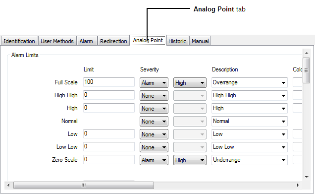
This section explains how to configure analog point properties that are common to many analog points. Most of these properties are displayed on the Analog Point tab of the Analog Point Form (on some advanced drivers, these properties are displayed on a separate tab).

You can use the Analog Point tab to:
- Configure the Limits for an Analog Point, including (if required):
- Use Hysteresis to Specify the Hysteresis - the Minimum Value Change that can Clear an Alarm from clearing an alarm
- Define how Over Range and Under Range Values are Processed
- Define whether an Analog Point’s Limits can be Tuned
- Specify the Area of Interest Associated with a Point’s State-Related Alarms and Events. (Only applicable if the Area of Interest feature is enabled in ClearSCADA.)
- Specify any Alarm Limit Profiles
- Define the Appearance of an Analog Point’s Values
- Define whether an Analog Point can be Overridden
- Define the Criteria for a Significant Change in Value
- Detect whether an Analog Point has Stopped Changing
- Define an Analog Point’s Trend Settings.
Additionally, if the point is an analog output, you need to use the Control tab to:
If the point in an internal analog point, you need to use the Manual tab to:
(In addition to internal analog points, ClearSCADA also supports Variables. The type of database item that you add to ClearSCADA depends on that item’s intended functionality. For more information, see Variables in the ClearSCADA Guide to Core Configuration.)
In circumstances where the server uses separate alarm limits to the outstation, those limits are configured on the Master Station Alarm Limits tab of the Analog Point Form (see Master Station Alarm Limits).