Use Digital Points within the ClearSCADA database to represent measuring instruments or control devices that can be in any of a set number of states (see Single and Multi-Bit Digital Points). For example, a digital point might represent a pump that is either running or stopped, or a pipe valve that is either open or closed. The raw digital value is received from the measuring instrument and processed to define the state of the digital point.
You configure each digital point on your system by using the fields on the appropriate Digital Point Form. Each Form has several tabs, which you use to define different aspects of the point configuration.
Use this section, along with the appropriate driver documentation, for information on configuring the digital points on your system.
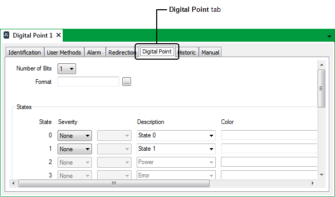
This section explains how to configure digital point properties that are common to many digital points. Most of these properties are displayed on the Digital Point tab of the Digital Point Form.

Each Digital Point Form has a Digital Point tab that you can use to:
- Define the Number of Bits for a Digital Point.
- Define the Format of a Digital Point’s Values.
- Define the Point States for a Digital Point.
- Specify the Area of Interest Associated with a Point’s State-Related Alarms and Events. (Only applicable if the Area of Interest feature is enabled in ClearSCADA.)
- Define whether a Digital Point can be Overridden.
- Define a Digital Point’s Trend Settings.
If the point is a digital output point, you need to use the Control tab to:
If the point is an internal digital point, you need to use the Manual tab to:
(In addition to internal digital points, ClearSCADA also supports Boolean Variables. The type of database item that you add to ClearSCADA depends on that item’s intended functionality. For more information, see Variables in the ClearSCADA Guide to Core Configuration.)