Many point types, such as analog and counter-type points, can support Multiple Point State Alarms. The Multiple Point State Alarms feature allows each type of point to have a user-defined number of ‘Point State’ Alarm Conditions, and to associate each state of a point with one of these conditions.
- When the Multiple Point State Alarms feature is not used (the default on many systems), each point has a single ‘Point State’ Alarm Condition, which is active when the value of the point is outside of the Normal operating range for that point. For instance, once an analog point value rises above the High limit, or falls below the Low limit, the ‘Point State’ Alarm Condition for that point becomes active.
- When the Multiple Point State Alarms feature is used for a particular point type, every point of that type will include all of the configured Alarm Conditions. This is regardless of a point’s specific configuration, within which only some of the Alarm Conditions might be used (any Alarm Conditions that are not used on a particular point will remain inactive).
So, for instance, the High state of an analog point might be associated with Alarm Condition ‘A’, and the High High state of the same point with Alarm Condition ‘B’. (The names of multiple ‘Point State’ Alarm Conditions are user configurable.) Under certain circumstances, multiple ‘Point State’ Alarm Conditions might be active simultaneously for a point. For instance, when the analog point mentioned above is in the High High state, both Alarm Condition ‘A’ and Alarm Condition ‘B’ are active. (If a further Alarm Condition, ‘C’, is configured, but is not used on this particular analog point, then Alarm Condition ‘C’ will remain inactive on that point.)
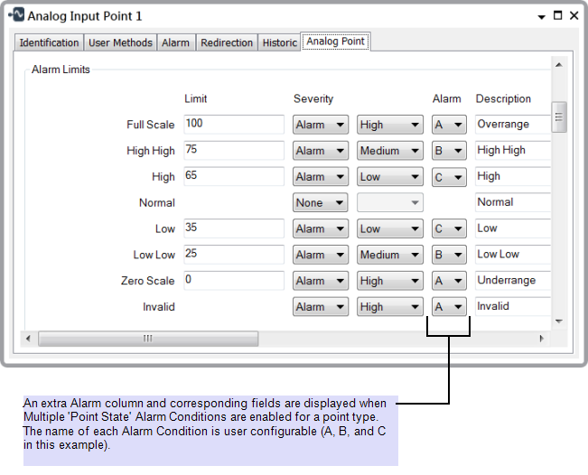
By default, the Multiple Point State Alarms feature is not enabled on a ClearSCADA system. To set up Multiple Point State Alarms for a particular type of point, use the Point State Alarms section of the ClearSCADA Server Configuration Tool (see Point State Alarms in the ClearSCADA Guide to Server Administration). Once enabled for a particular point type, an additional Alarm column is displayed within the Alarm Limits section of the Point Form for that type of point (see the example below). Use the Alarm field that corresponds to each limit to specify the particular ‘Point State’ Alarm Condition that is to be associated with that limit. (You can specify different combinations of Alarm Conditions for each point.)
Be aware that additional fields are displayed on the Point Form if you Use Multiple Point State Alarms in Conjunction with Areas of Interest.
Example:
Three ‘Point State’ Alarm Conditions are configured for the analog points on the DNP3 driver (the point type CDNP3AnalogIn). The Alarm Conditions are labelled A, B, and C.
As a result, an extra Alarm column is displayed within the Alarm Limits section of the Point Form for each DNP3 analog input point.
The Alarm combo box for each limit is used to select the required Alarm Condition for that limit. So, for the DNP3 analog input point shown below, the Full Scale, Zero Scale, and Invalid states are designated as level ‘A’ alarms; the High High and Low Low states as level ‘B’ alarms; and the High and Low states as level ‘C’ alarms.

Each limit is associated with a separate ‘Point State’ Alarm Condition. As such, when the value of the point rises past the High limit, the ‘Point State C’ Alarm Condition becomes active.
If the value of the point continues to rise past the High High limit, the ‘Point State C’ Alarm Condition remains active; additionally, the ‘Point State B’ Alarm Condition becomes active, and so both Alarm Conditions are now active.
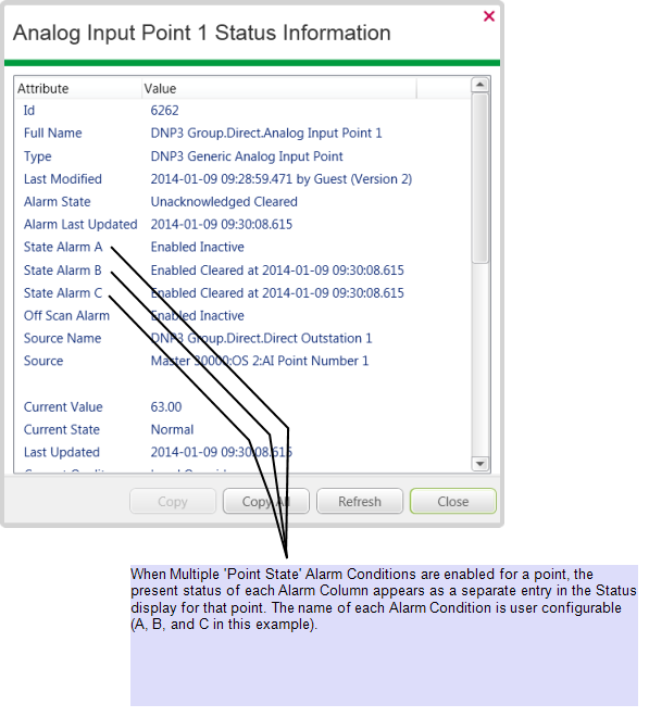
The present status of each Alarm Condition is listed in the Status display for the point:
