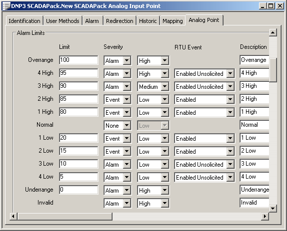
Use the fields within the Alarm Limits section of the Analog Point tab to set limits for a DNP3 SCADAPack analog point and specify whether an alarm or event is generated if the point’s value exceeds those limits.

The following properties are common to DNP3 SCADAPack analog points:
- Overrange—Use to specify the maximum expected engineering value of the point, and the generation of alarms or events if the point value is greater than this value. (Overrange is equivalent to the Full Scale property of analog points on many other drivers.)
- 1 High, 2 High, 3 High, and 4 High—Use to specify whether ClearSCADA generates an alarm or event whenever the points value rises to, or goes above, the corresponding Limit value.
- Normal—Specifies whether ClearSCADA generates an event whenever the point returns to its normal operating range (the range between the 1 High and 1 Low Limit values).
- 1 Low, 2 Low, 3 Low, and 4 Low—Use to specify whether ClearSCADA generates an alarm or event whenever the points value falls to, or goes below, the corresponding Limit value.
- Underrange—Use to specify the minimum expected engineering value of the point, and whether ClearSCADA generates an alarm or event if the point value is less than this value. (Underrange is equivalent to the Zero Scale property of analog points on many other drivers.)
- Invalid—Use to specify whether ClearSCADA generates an alarm or event whenever the point’s value is reported as invalid by the outstation. Use the fields associated with this state to define the properties should the analog to digital conversion process fail in the outstation.
For further information on configuring limits, see Configure the Limits for an Analog Point in the ClearSCADA Guide to Core Point Configuration.
NOTE: If any High or Low limits are profile-controlled, the unused ‘fixed’ Limit field within the Alarm Limits section of the tab will be ‘grayed out’ and unavailable for use. You still use the other fields within the Alarm Limits section to configure other properties associated with such limits. For more information, see Specify Whether any Profiles are Used to Change a Point’s Limits or Current Value.
If the point’s PointData Class is set to Class 1 Event, Class 2 Event or Class 3 Event and the point’s limit has a Severity of Event or Alarm, the SCADAPack E outstation can be configured to generate and store an event in its Event Buffer when the corresponding alarm limit is transgressed. The event is stored in the outstation’s Event Buffer according to the Point Data Class of the point (see Configure Common Properties of DNP3 SCADAPack Points). Use each limit’s RTU Event field to specify whether the outstation generates an event whenever the corresponding Alarm Limit is exceeded and if so, whether it just stores that event, or immediately generates an unsolicited message (see Specify Whether a Class n Event Triggers an Unsolicited Message).
Use the Out of Range RTU Event field at the bottom of the Alarm Limits section to Specify how the SCADAPack Outstation Handles Underrange, Overrange and Invalid RTU Events.
(RTU Event fields are ‘grayed out’ and unavailable for use if the point’s Point Data Class is set to Local or Class 0 Static Only.)