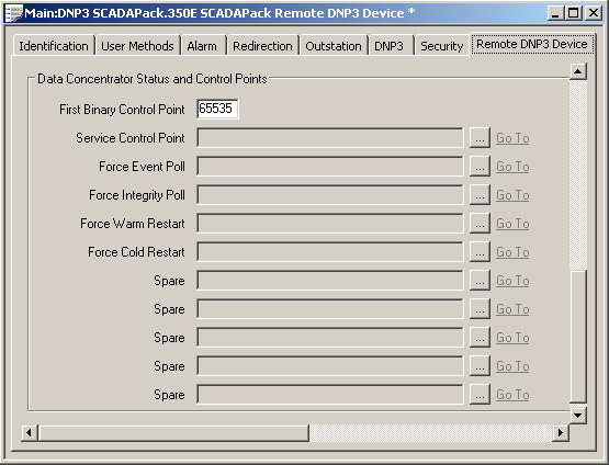
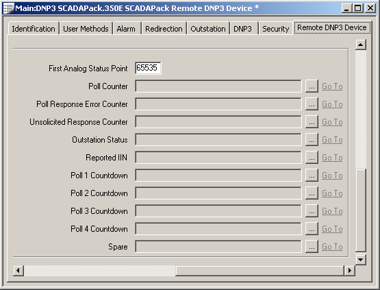
Use the fields within the Data Concentrator Status and Control Points section of the Remote DNP3 Device tab to specify the points that the remote outstation’s parent outstation (data concentrator) uses to control or monitor the status of this remote outstation. You can only specify points that have their Point Type set to User (Derived), and have their Outstation specified as this remote outstation’s parent outstation.
The fields within this section are ‘grayed out’ and unavailable for use if the Polled By field is set to Master Station (see Specify Which Devices Scan a Remote Outstation).
Where a remote outstation is polled by both its parent outstation and the ClearSCADA server, the properties within this Data Concentrator Status and Control Points section only apply to the remote’s parent outstation.
The fields on the left-hand side of the Data Concentrator Status and Control Points section of the tab are used to specify the DNP3 SCADAPack binary or pulse points that the data concentrator uses to control activity on this remote outstation.

The Point Numbers of the points in these fields have to be consecutive, with the Service Control Point having the lowest Point Number (n), the Force Event Poll point having the Point Number (n + 1), and so on. In each case, the point has to have its Point Type set to User (Derived) in order to be a valid control point (see Configure Common Properties of DNP3 SCADAPack Points).
Use the First Binary Control Point field to specify the Point Number of the Service Control Point. Providing that the points exist in the database, ClearSCADA will automatically populate the entries in the left-hand block of fields, once you specify this Point Number and save the configuration. As with other configuration in ClearSCADA, a message area will be displayed at the bottom of the Form should any of the control points have invalid configuration (such as an incorrect Point Type).
NOTE: If the remote outstation is in an Instance of a Group Template, enable the appropriate Property Overrides to allow the First Binary Control Point to be specified on a per-Instance basis.
The points are allocated in ascending address order, as follows:
- Service Control Point—The binary point that controls scanning of this remote outstation by the data concentrator. The data concentrator polls the remote whenever this point has a value of 1. Controlling the point to a value of 0 will cause polling to stop.
- Force Event Poll—The NULL Pulse Action that is used to trigger a Class 1, 2, and 3 event poll of this remote outstation. A positive pulse triggers the poll.
- Force Integrity Poll—The NULL Pulse Action that is used to trigger an Integrity poll of this remote outstation. A positive pulse triggers the poll.
- Force Warm Restart—The NULL Pulse Action that is used to trigger a Warm Reset request. A positive pulse triggers the request.
- Force Cold Restart—The NULL Pulse Action that is used to trigger a Cold Reset request. A positive pulse triggers the request.
- Spare—Any other binary points that exist within the DNP3 point number range n + 5 to n + 9 (where n is the point number specified in the First Binary Control Point field). The functionality of these points is undefined in the outstation.
The fields on the right-hand side of the Data Concentrator Status and Control Points section of the Remote DNP3 Device tab are used to specify the DNP3 SCADAPack analog points that monitor the poll (scan) status of this remote outstation.

The Point Numbers of the points in these fields have to be consecutive, with the Poll Counter point having the lowest Point Number (n), the Poll Response Error Counter point having the Point Number (n + 1), and so on. If any statuses are not being modified and those fields are therefore left blank, the Point Numbers of the points specified in the remaining fields have to continue the Point Number run as if those fields were populated. So if the Poll Counter point has Point Number n, the Point Numbers have to increment consecutively, culminating with the point used to monitor Poll 4 Countdown, which has to have the Point Number n + 8 (or the Spare point, if one exists, that has the Point Number n + 9). The point in each has to have its Point Type set to User (Derived) in order to be a valid status point (see Configure Common Properties of DNP3 SCADAPack Points).
Again, providing that the points exist in the database, ClearSCADA will automatically populate the entries in this block of fields, once you specify the address of the First Analog Status Point and save the configuration. The address that you specify in the First Analog Status Point field has to be the address of the point that will be used as the Poll Counter.
NOTE: If the remote outstation is in an Instance of a Group Template, enable the appropriate Property Overrides to allow the First Analog Status Point to be specified on a per-Instance basis.
ClearSCADA will then assign the block of points, in ascending address order, as follows:
- Poll Counter—The analog point that is used to monitor the number of successful polls of this remote outstation.
- Poll Response Error Counter—The analog point that is used to monitor the number of unsuccessful polls (poll requests that the data concentrator has sent to this remote outstation, but that have not resulted in a successful poll).
- Unsolicited Response Counter—The analog point that is used to monitor the number of unsolicited messages that the data concentrator has received from this remote outstation.
NOTE: To reset the Poll Counter, Poll Response Error Counter, or Unsolicited Response Counter from ClearSCADA, configure a DNP3 SCADAPack Analog Output point in the database and use that point to control the counter value to zero (or whichever value is required).
- Outstation Status—The analog point that indicates the current status of this remote outstation, as received by the data concentrator. This analog point should be configured to have the following values:
- 0—Outstation Not Found
- 1—Finding Outstation
- 2—Initializing Outstation
- 3—Failed Communications
- 4—Outstation Online
- 5—Outstation Disabled.
For more information on the status that these values represent, see the SCADAPack E Data Concentrator Technical User Reference Manual.
- Reported IIN—The analog point that indicates the latest remote outstation IIN value to be received by the data concentrator.
- Poll n Countdown—The analog points in the Poll 1 Countdown to Poll 4 Countdown fields are used to indicate the time left, in seconds, before the data concentrator sends specific poll requests to this remote outstation. Each countdown is for the corresponding poll that is represented by the Poll Rate 1 to Poll Rate 4 fields, in the Data Concentrator Polling section of the tab (see Configure the Data Concentrator Polling). The type of poll undertaken differs, depending on the specified poll Type.
Example:
A Remote E Outstation has this configuration:
Polled By: Data Concentrator
Type: Background Poll
Poll Rate 1: 10S (A 10-second Background poll rate)
Poll Rate 2: 30S (A 30-second Must Poll rate)With this configuration, analog points need specifying in just the Poll 1 Countdown and Poll 2 Countdown fields—the other countdown fields can be left blank. The point specified in the Poll 1 Countdown field will monitor the time left before the data concentrator undertakes the next background poll of the remote outstation (as per the Poll Rate 1 field). The point specified in the Poll 2 Countdown field will monitor the time left before the data concentrator undertakes the next ‘Must Poll’ Integrity poll (as per the Poll Rate 2 field).
Another Remote E Outstation has this configuration:
Polled By: Data Concentrator
Type: Class Poll
Poll Rate 1: 20S (A 20-second Class 1 event poll)
Poll Rate 2: 30S (A 30-second Class 2 event poll)
Poll Rate 3: 40S (A 40-second Class 3 event poll)
Poll Rate 4: 50S (A 50-second Integrity poll)With this configuration, an analog point needs specifying in each of the four Poll n Countdown fields. The point specified in the Poll 1 Countdown field will monitor the time left before the data concentrator undertakes the next Class 1 event poll of the remote outstation (as per the Poll Rate 1 field); the point specified in the Poll 2 Countdown field will monitor the time left before the data concentrator undertakes the next Class 2 event poll (as per the Poll Rate 2 field), and so on.
- Spare—Any analog point that exists with the Point Number n + 9 (where n is the point number specified in the First Analog Status Point field). The functionality of this point is undefined in the outstation.
For more information on status and control points, see the SCADAPack E Data Concentrator Technical User Reference Manual.