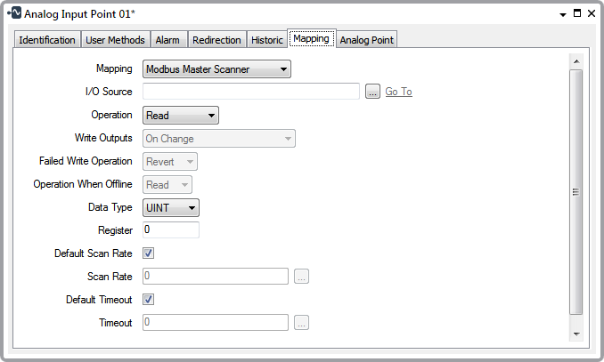
To map to point data on a Modbus slave device, you need to specify the following:

I/O Source
Operation
Use this combo box to specify whether the SCADAPack E outstation reads from, or writes to, the point on the slave device. Select from Read or Write.
Write Outputs
This combo box will only be available if you set the Operation to Write. Use this combo box to specify when the SCADAPack E outstation writes to the point on the Modbus slave driver. Select from the following:
At Scan Rate
Write to the point at the Default Scan Rate configured for the slave device Configuring a DNP3 SCADAPack E Modbus Slave Device or at the Scan Rate defined on this form (see Scan Rate below).
On Change
Write to the point when the point value changes.
At Scan Rate and On Change
Write to the point at both the Default Scan Rate configured for the slave device, and when the point value changes (see Configuring a DNP3 SCADAPack E Modbus Slave Device ).
Failed Write Operation
This combo box will only be available if you set the Operation to Read/Write. Use this combo box to specify the operation that should occur when a write failure occurs. Either Revert to the previous operation or Retain the current operation.
Operation When Offline
This combo box will only be available if you set the Operation to Read/Write. Use this combo box to specify the operation the outstation should perform while the point is offline.
Data Type
Use this combo box to specify the format of the point value. Select from the following:
Discrete
The value is formatted as a discrete number (binary points only)
INT
The value is formatted as signed 16-bit data. Each INT comprises 1 Modbus register.
UINT
The value is formatted as unsigned 16-bit data. Each UNIT comprises 1 Modbus register.
DINT
The value is formatted as signed 32-bit data. Each DINT comprises 2 Modbus registers (analog points only)
UDINT
The value is formatted as unsigned 32-bit data. Each UDINT comprises 2 Modbus registers (analog points only)
Real
The value is formatted as an IEEE 32-bit single-precision floating point value. Each REAL comprises 2 Modbus registers (analog points only).
Register
Specify the register address on the Modbus slave device to which the point's values are mapped. The valid addresses are as follows:
| Value Type | 5-digit Addressing | 6-digit Addressing |
|---|---|---|
| 1-bit output | 00001-09999 | 000001-065536 |
| 1-bit input | 10001-19999 | 100001-165536 |
| 16-bit input | 30001-39999 | 300001-365536 |
| 16-bit output | 40001-49999 | 400001-465536 |
For more information about register addressing on the Modbus slave device, see Configuring a DNP3 SCADAPack E Modbus Slave Device
Bit
This field is only available for binary points. The field is not available if you set the Data Type to Discrete. Specify the bit in the 16-bit Register to which the point's value is mapped. Enter the bit number as an offset into the register.
Default Scan Rate
Use this check box to set the frequency rate at which the SCADAPack E outstation scans the point. Select the check box to accept the Default Scan Rate defined for the Modbus slave device (see Configuring a DNP3 SCADAPack E Modbus Slave Device ). Clear the check box to specify a different rate in the Scan Rate field (see below).
Scan Rate
Enter the frequency rate at which the SCADAPack E outstation scans the point. Specify the rate in the OPC Time Format. Enter the rate directly in the field (see Specify a Time Period in the OPC Time Format in the ClearSCADA Guide to Core Configuration) or use the Interval Window to specify the rate that you require.
Default Timeout
Use this check box to set the amount of time that the SCADAPack E outstation should wait for a response when it scans the point on the Modbus slave device. If the outstation does not get a response in this time, the outstation will try the scan again until it exceeds the Timeout Retries count. For more information about the Timeout Retries, (see Configuring a DNP3 SCADAPack E Modbus Slave Device ). If the outstation still cannot get a response after the retries, it will determine that it cannot communicate with the device. Select the check box to accept the Default Timeout defined for the device (see Configuring a DNP3 SCADAPack E Modbus Slave Device ). Clear the check box if you want to specify a different timeout interval in the Timeout field (see below). The timeout value that you enter is for each scan.
Timeout
Use this check box to set the amount of time that the SCADAPack E outstation should wait for a response when it scans the point on the Modbus slave device. If the outstation does not get a response in this time, the outstation will try the scan again until it exceeds the Timeout Retries count. For more information about the Timeout Retries, (see Configuring a DNP3 SCADAPack E Modbus Slave Device ). If the outstation still cannot get a response after the retries, it will determine that it cannot communicate with the device. Specify the time interval in the OPC Time Format. Enter the interval directly in the field (see Specify a Time Period in the OPC Time Format in the ClearSCADA Guide to Core Configuration) or use the Interval Window to specify the interval that you require. The timeout value that you enter is for each scan.