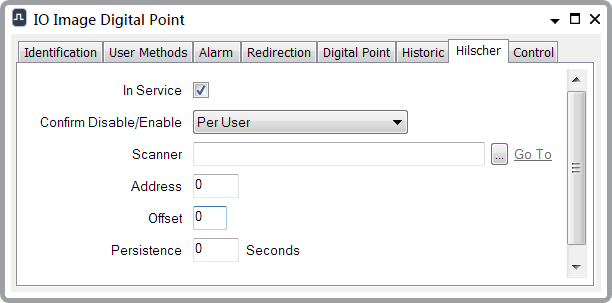
Use the fields at the top of the Hilscher tab to configure the general point properties. Some of these fields are common to points on many simple drivers (see Configure Common Point Properties in the ClearSCADA Guide to Simple Drivers). Fields that are specific to points on the Hilscher driver are explained below.

- Scanner—Use to specify the Scanner that scans the point’s data. Select the browse button to display a Reference browse window. For a Hilscher IO Image Digital point, select the appropriate Hilscher IO Image Scanner; for a Hilscher Profibus FMS Digital point, select the appropriate Hilscher Profibus FMS Scanner.
- Address—Use to specify the address of the point on the Hilscher card. For multi-byte points, this is the lowest (starting) byte. This is the address of the point within the Hilscher card’s memory.
With a Hilscher IO Image Scanner, ClearSCADA scans the whole card, and extracts the data from the relevant address(es) on that card.
With a Hilscher Profibus FMS Scanner, ClearSCADA scans a specified number of elements within a data array on a device (see Configure the Properties of a Profibus FMS Scanner). The point Address is an offset from the Scanner’s Data Start index.
- Offset—Use to specify the starting bit of the data within the specified byte. Enter the required offset, in the range 0 to 7.
An example at the end of this section shows how the Address and Offset are used by ClearSCADA (see below).
- Persistence—Specify the time that the Hilscher driver waits before it reports a change of state. Enter the time in seconds. This allows the driver to ignore fleeting changes in point state.
Example:
On a particular ClearSCADA system, a Hilscher Profibus FMS Scanner is given this configuration:
Object Data Type:BOOL (Boolean data)
Data Start:3
Data Length:;12
Thus, the Scanner scans elements 3 to 14 on the FMS device with which the Scanner is associated.
A Digital Point that uses the above Scanner is given this configuration:
Number of Bits:2
Address::4
Offset:3 (indicating that the starting bit is the third bit in the above Address)
To obtain the value of this point from the above scanned range, ClearSCADA extracts the data from the 3rd bit within element 6 through to the 3rd bit in element 7.