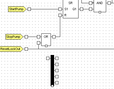
ClearSCADA allows you to use Ladder Diagrams within Function Block Diagrams. This is useful as it allows you to create Logic sequences that are more appropriate to Ladder Logic and connect them to the Logic in a Function Block Diagram.
Before you create a Ladder Diagram in a Function Block Diagram, you should familiarize yourself with the concepts and design of Ladder Logic (see Ladder Diagrams).
To create a Ladder Diagram in a Function Block Diagram:
- Right-click on the background of the Function Block Diagram.
A context sensitive menu is displayed. - Select one of these options:
- Add Left Power Rail—Adds a left power rail to the diagram. The left power rail is the source of the values (that is, it needs to be connected to inputs).
- Add Right Power Rail—Adds a right power rail to the diagram. The right power rail is the result of the Ladder Diagram (that is, it needs to be connected to outputs).
The rail is added to the diagram.

You can add coils and contacts to the diagram and connect them to the rails. This is done in exactly the same way as when you add contacts and coils to a Ladder Diagram.
You can then connect the rails to other Logic components in your Function Block Diagram. Connect the rails via the connection boxes on the outside of the rails:
