Function Block Diagrams have inputs and outputs, and also contain functions, function blocks, conversions etc. Each Function Block Diagram uses its functions, function blocks etc. to determine outputs based on the values for its inputs.
By creating connections between the various function block components, you can create complex behavior Logic.
Example:
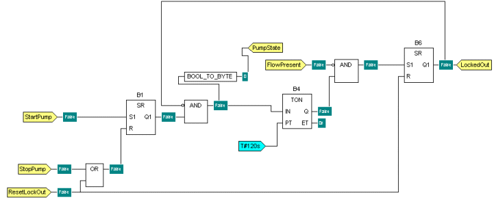
For example, the following Function Block Diagram is used to control a pump in the water industry:

In this example, the states of the four input points (StartPump, StopPump, ResetLockOut, and FlowPresent) are used to determine whether the pump starts, stops, or is reset. The connections between the various functions and function blocks define the behavior that is provided by the Function Block Diagram:
- If the StartPump input is true, the pump will start (PumpStart output is true) as long as the FlowPresent value is true and the pump is not locked out (LockedOut value is false).
- If the pump is locked out (LockedOut value is true), the PumpStart output will not change in response to the StartPump or StopPump inputs—it will only change after the ResetLockOut input has become true and the LockedOut output is false.
- The PumpState output can only be true if the StartPump input is true, and the FlowPresent input is true, and the LockedOut output is false. This means that the pump will only be switched on when
- it has a start signal
- can detect a flow
- is not locked out
There is a time delay between the StartPump and StopPump signals affecting the state of the PumpState output. This means that fleeting state changes will not affect the outputs.