Functions used in Ladder Diagrams and Function Block Diagrams have an extra input and output. The extra input is EN and the extra output is ENO:
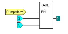
- EN—The EN input represents ENABLED and it is used to control whether the function is performed. When the EN input is used, the function is only performed if the EN input is true. For example, if the EN input is used on an ADD function, the output of the ADD function will only be the sum total of its two normal inputs if its EN input is true. If the EN input is false, the output of the ADD function will be 0, irrespective of its inputs.
Example:

The output of the ADD function is 0, despite the inputs being 2 and 5. The output is 0 instead of 7 as the ADD function is not performed due to the PumpAlarm direct variable being in state 0 (false).
If the PumpAlarm direct variable changes to state 1 (true) the output of the ADD function will be 7 (2+5).
- ENO—The ENO output represents ENABLED OUTPUT and it is used to show that a function has executed successfully. If the ENO value is True, the function has executed successfully; if the ENO value is False, the function has not executed successfully and there is an error such as an arithmetic overflow.
You can set a function to be both EN and ENO at the same time. This allows you to control whether the function is performed and to determine whether it is executed successfully. By chaining the ENO output of one function to the EN input of another, you can create a flow of functions that are only executed if the previous function was successful.
In ST, you can refer to the EN and ENO input and outputs in the same way as other variables. For example:
- VAR_INPUT
- EN: BOOL := 0;
- END_VAR
- VAR_OUTPUT
- ENO : BOOL;
- END_VAR