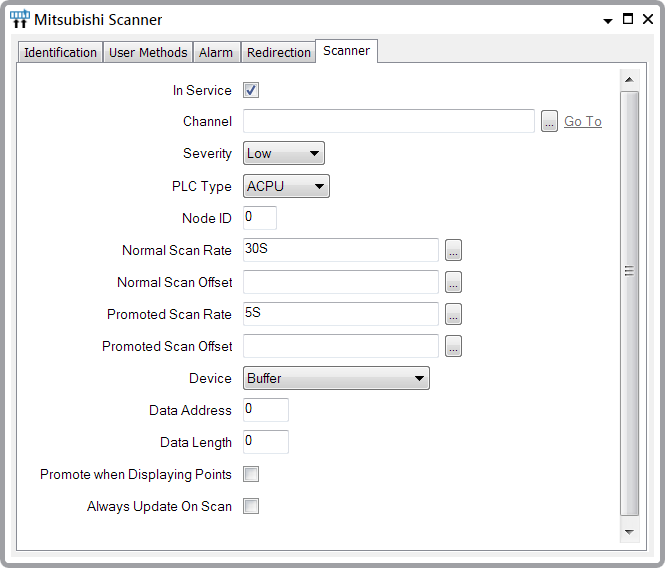
Use the fields on the Scanner tab of the Mitsubishi Scanner Form to define the general and Mitsubishi-specific properties for a scanner. Many of the fields on this tab are common to many scanners (see Configuring Scanners on Simple Drivers in the ClearSCADA Guide to Simple Drivers). Those fields that are specific to scanners on the Mitsubishi driver are described below.

- Channel—Use to specify the channel through which the scanner transmits data. Use the browse button to display a Reference Browse window. From the window, select the channel that the scanner uses to communicate with a Mitsubishi PLC or Mitsubishi Slave.
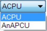
- PLC Type—Use this combo box to specify the type of PLC that the Mitsubishi scanner is to scan.

The mode of addressing varies with the type of Mitsubishi Slave or PLC (see Mitsubishi Data Address Ranges).
- Node ID—Use to specify the ID of the scanned slave’s Mitsubishi node.
- Device—Use to specify the type of data that is to be scanned. The option that you specify determines the area of memory that the scanner scans on the Mitsubishi Slave or PLC.

- Data Address—Use to specify the address from which the scanner is to start scanning data, within the address range that is allocated to the specified Device.
For Word Devices, specify the offset into the device, in multiples of 16-bit Words.
For Bit Devices, specify the offset into the device, in Bits.
For information on Device address ranges and the unit that each Device supports, see Mitsubishi Data Address Ranges.
- Data Length—Use to specify the number of addresses that are to be scanned in the PLC. The addresses are scanned as a block, starting at the Data Address specified above. You need to set the Data Length so that it encompasses each of the point locations that you want to scan using this scanner. (You specify the individual point locations within this range, using the Word Offset and Bit Offset fields on the individual Point Forms.)
Example:
A scanner has this configuration:
PLC Type: ACPU
Device: Input X
Data Address: 64
Data Length: 2This results in the scanner scanning 32 points from Input X device address X00040 to Input X device address X0005F.
For further examples showing how you might configure the Device, Data Address, and Data Length properties, see Configuration Examples.