This example demonstrates how ClearSCADA might be configured to scan Internal Relay data on a Mitsubishi MELSEC A PLC.
In the example, a Mitsubishi Scanner is used to scan the address range M0010 to M0021 in Internal Relay M. The example demonstrates how a digital point might be used to represent 2 bits of data that reside at address M0014 in that Internal Relay.
Example:
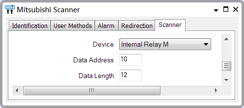
A scanner scans several Internal Relays on a Mitsubishi PLC. Within ClearSCADA, the Scanner has this configuration (the PLC type is set to ACPU):

This configuration determines that the scanner scans the Internal Relay M Device range M0010 to M0021 within the PLC (Internal Relays have decimal notation in the PLC).
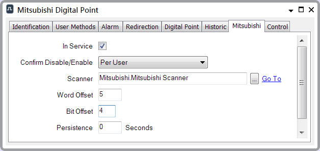
Within this address range, a 2-bit digital point is to represent the data that is located at address M0014, starting at the fourth bit within that Word, and continuing to the fifth bit. (Each Internal Relay comprises 16 bits of data.) Within ClearSCADA, the 2-bit digital point has this configuration:

In order to read the value of this point, the scanner extracts the data from bits 4 and 5 of Internal Relay M Device M0014.
Operators can confirm the address range that the scanner is scanning by looking at the Source attribute on, for example, a List (to display scanner details in List format from the Queries Bar, you filter the constraints on the Point Sources List):

They can also use the point’s Source attribute to confirm the type of data and address of the Link Register with which the individual digital point is associated:
