Modbus Slaves use Value Maps to store ‘point’ data. Each Source within a Slave can store data using a different set of Value Maps.
The Value Maps that are required for the Slave need to have been created and suitably configured on your system (see Using Value Maps to Represent Modbus Data Address Ranges in this guide, and see Configuring Value Maps in the ClearSCADA Guide to Core Configuration).
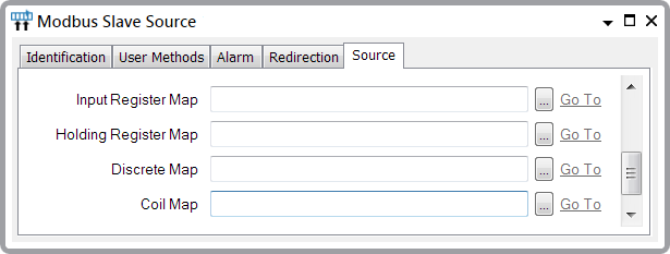
Use these Map fields on the Source tab to define the Value Maps that are used by a particular Source:

- Input Register Map—Specify the Value Map that is used to store calculated 16-bit input values. Use the browse button to display a Reference browse window, and select the required WORD Value Map from the window.
- Holding Register Map—Specify the Value Map that is used to store calculated 16-bit output values. Use the browse button to display a Reference browse window, and select the required WORD Value Map from the window.
- Discrete Map—Specify the Value Map that is used to store discrete single-bit input values. Use the browse button to display a Reference browse window, and select the required BIT Value Map from the window.
- Coil Map—Specify the Value Map that is used to store discrete single-bit output values. Use the browse button to display a Reference browse window, and select the required BIT Value Map from the window.
Leave the fields blank for any Map types that are not used by this Source.
Each field and associated Value Map represents a different type of data within a Modbus PLC. For example, if a Value Map is specified in the Input Register Map field, above, the entries that populate the Value Map would emulate Input Register data in a Modbus PLC. For more information, see Using Value Maps to Represent Modbus Data Address Ranges.
For an example of how you might use a Value Map to represent Modbus data and how you might map that data to a Modbus Slave Source, see Example Configuration.