This example is intended to show a typical use of the Random Generator. In this particular example the Random Generator is used with the ClearSCADA Advanced Modbus and Modbus Slave drivers, but it can be used to simulate data for any suitable device in ClearSCADA.
Example:
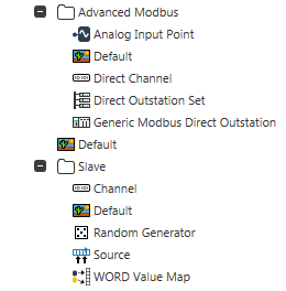
This example makes use of the Advanced Modbus driver and a Modbus Slave outstation, as shown in the Database Bar below:

The Generic Modus Direct Outstation has been configured to communicate with the Modbus Slave Source so that they both have the same Modbus address. The channels are set up to allow the Outstation to talk to the Slave. For more information, see the ClearSCADA Guide to the Advanced Modbus Driver and the ClearSCADA Guide to the Modbus Slave Driver.
The Slave outstation emulates a Modbus PLC. The Slave has a Random Generator to emulate the data that would be generated at a PLC in the field. In this example, the data to be used is the sine wave output from the Random Generator.
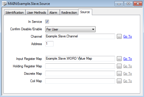
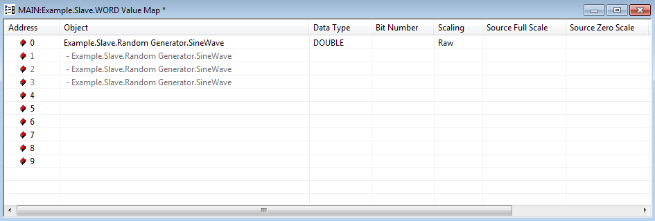
The Slave Source is configured to use WORD Value Map data as Input Register data. The WORD Value Map is configured to emulate the Input Register memory area. (WORD Value Map address 0 is the equivalent of Modbus register address 1 or 30001, and WORD Value Map address 3 is the equivalent of Modbus register address 4 or 30004.)

You can add the sine wave output from the Random Generator to the Value Map by dragging the Sine Wave property from Random Generator on the OPC Data Bar to the relevant line of the Value Map.
For more information, see Working with the OPC Data Bar in the ClearSCADA Guide to Core Configuration, and see Configuring Value Maps in the ClearSCADA Guide to Core Configuration.

The Generic Modbus Analog Point is now configured to reference Address 0 in the Value Map Modbus address 30001 and is configured with the Data Type of DOUBLE.
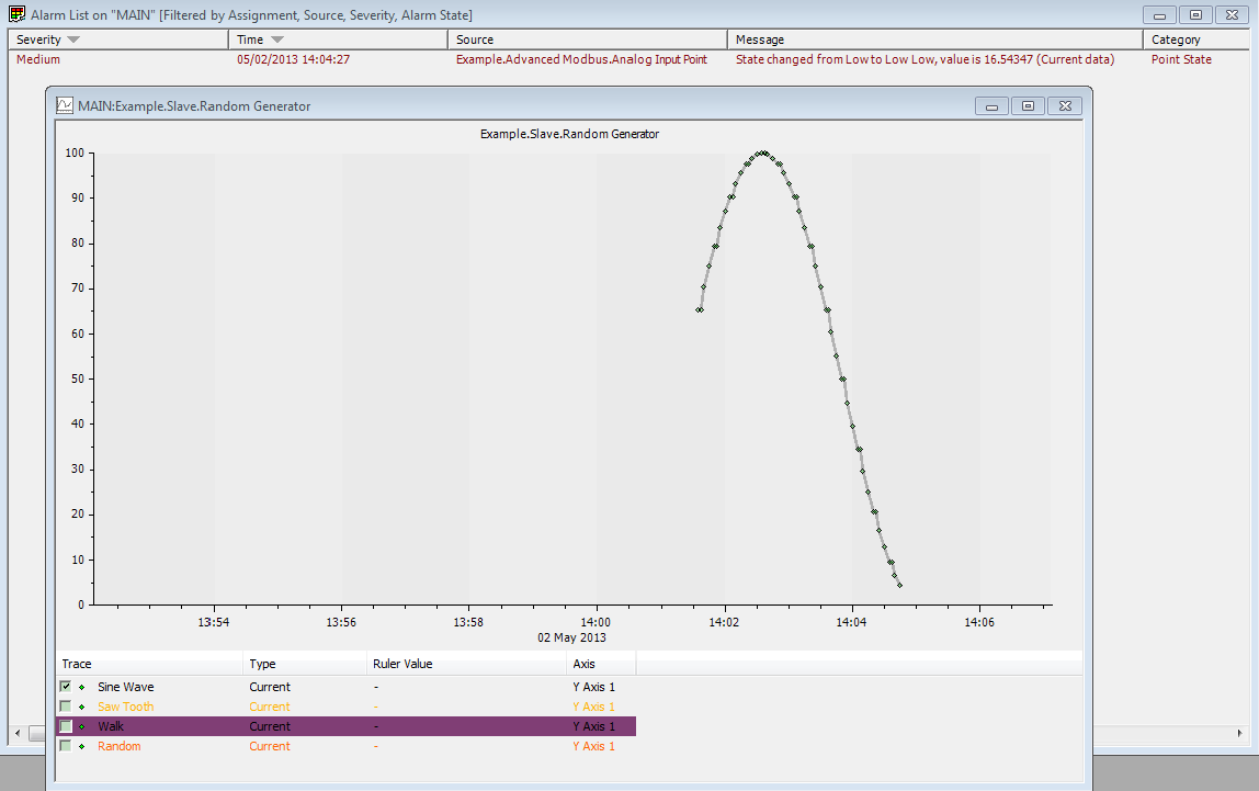
With the default alarm settings on the Input Point, the output of the Random Generator can be seen generating the appropriate alarms:
