Associated with: SCADAPack Modbus Flow Runs
Security permission required to access this pick action: Override/Release
NOTE: To adjust the input values before changing a Dual Chamber Orifice Plate, use the Start Orifice Plate Change pick action, rather than the Force Inputs pick action.
To enable a Flow Computer to continue to calculate gas, liquid or water flow data while any of its sensors are being calibrated, a Flow Run can be configured to use ‘forced’ values in its calculations. Once the sensors are calibrated, the flow calculations revert to using live values and the forced values are disabled.
You can ascertain the present values of a Flow Run’s Forced inputs by looking at the Forced Differential Pressure (or Forced Pulse Rate for AGA-7 calculations), Forced Static Pressure, and Forced Temperature attributes on the Flow Run’s Status Display (see SCADAPack Modbus Specific Status Display Attributes).
You can then use the Flow Run’s Force Inputs pick action to either force the inputs, or to remove existing forcing, as required. (When any sensors are being calibrated, use the Force Inputs pick action just before calibration, to change the inputs to Fixed Values. On completion of the calibration, use the Force Inputs pick action again, to revert the inputs back to using live Current Values.)
UNEXPECTED BEHAVIOR OF APPLICATION
Ensure that the relevant sensors or registers are connected before using the Force Inputs pick action to end forcing and revert inputs back to live values.
If the live input values are provided by local registers but those registers are not connected beforehand, the input values will be undefined.
If the live input values are provided by sensors but those sensors are not connected beforehand, the Flow Computer will report communication lost. If supported by the version of RealFLO, the Flow Computer will then use the last known good value or the Default Value specified in the configuration. This might result in the flow calculation producing a different result to that which is expected.
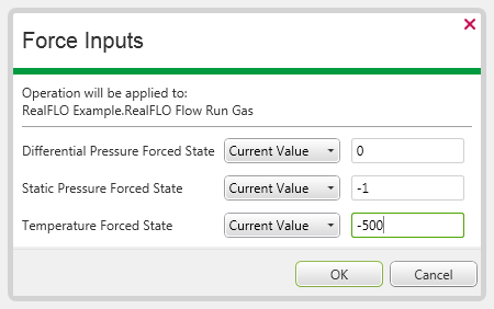
- Select the Force Inputs pick action to display the Force Inputs window.
The window displays the present state and value of each input on the Flow Run. The fields vary, depending on the type of Flow Calculation that the Flow Run performs (the Differential Pressure Forced State is replaced with Pulse Counter on Flow Run’s that perform AGA-7 Flow Calculations).

- For each input, use the left-hand combo box to specify the type of input. Choose from:
- Current Value—The input is fixed at the current live sensor value, which is displayed in the right-hand field. (The value shown in the right-hand field is for information only—if you want to specify a different value to that shown, use the left-hand combo box to specify a Fixed Value instead of a Current Value (see below).)
- Fixed Value—The input is a fixed value. Use the right-hand field to specify the required input value.
- Remove—Disables any forcing. The input reverts to its live sensor value.
- No Change—The input is to continue as a live or fixed sensor value or a forced value (whichever presently applies).
For options other than Fixed Value, the values in the corresponding right-hand fields are displayed for information only—ClearSCADA ignores any changes that are made to such values.