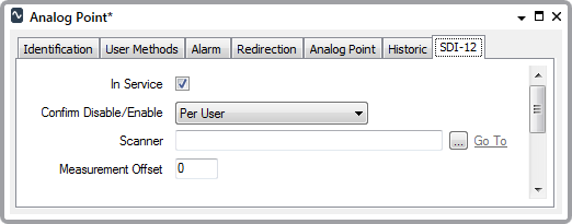
Use the fields at the top of the SDI-12 tab to configure the SDI-12 specific point properties. Some of these properties are common to points on many simple drivers—for information, see Configure Common Point Properties in the ClearSCADA Guide to Simple Drivers. Properties that are specific to analog points on the SDI-12 driver are explained below.

- Measurement Offset—Use to specify the location of this particular measurement, as an offset into the data that the scanner is to extract from the sensor. The range varies, depending on the number of sensor readings that the scanner is configured to scan. As such, you need to specify the required offset from within the range:
0 to (Scanner’s Data Length - 1)
where 0 is the first measurement, 1 is the second measurement, and so on.
(The Data Length is specified on the SDI-12 Scanner Form (see Configure the Sensor Properties).)
Example:
An SDI-12 Scanner includes this configuration:
Command Type: Measurement
Data Length: 3Three SDI-12 Analog Points are configured in the ClearSCADA database and are associated with the scanner. Each analog point is given a different Measurement Offset, to represent the three separate readings that the scanner retrieves from the sensor.
The analog point that represents the first reading is given a Measurement Offset of 0, the analog point that represents the second reading is given a Measurement Offset of 1, and the analog point that represents the third reading is given a Measurement Offset of 2.