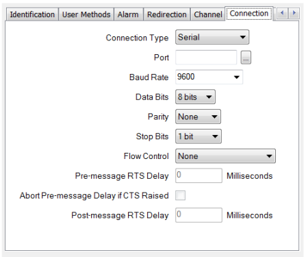
For a channel to represent a Serial connection, set the channel’s Connection Type field (if displayed) to ‘Serial’. (The Connection Type field is only displayed for channels that support a choice of connection types—see Configure a Channel’s Connection Type.)
Configure the required connection properties using the fields that are displayed on the rest of the tab. Channels that represent Serial connections have a combination of these fields:

- Port—Use to define the physical port to which the line represented by the channel is connected. For example, COM1.
Select the browse button to display a Reference browse window and then select the required port from the window.
If you are using an advanced driver channel to eavesdrop both Rx and Tx communications on a system, you need to enter both ports in this field. Ensure that you specify the Rx port first, using the format <Rx port>, <Tx port>. For example COM1,COM2 where COM1 is the receiving port, and COM2 the transmitting port. For more information on eavesdropping, see Using Eavesdropping to Test a New Server’s Configuration in the ClearSCADA Guide to Advanced Drivers.
- Baud Rate—Use to define the speed of data transfer to be used by the channel. This has to match the Baud Rate that is supported by your communications equipment.
Specify a baud rate that corresponds with the baud rate of the communications equipment that is connected to the selected port. Either use the combo box to select a baud rate from the supplied list, or enter the required rate directly in the field. If the operating system, serial port drivers and hardware cannot implement the specified baud rate, the operating system or serial port hardware (UART) may automatically use the nearest supported baud rate to that specified.
- Data Bits—Select the number of bits that is used to transmit and receive each byte of data. This has to match the Data Bits configuration of your communications equipment (see Data Bits and Stop Bits).
- Parity—Use to define how the Parity bit is set when Parity error checking is supported. This has to match the Parity setting of your communications equipment (see Parity).
- Stop Bits—Select the number of stop bits in each byte. The number of Stop Bits defines the number of bits that are placed between each character in the transmitted and received data. This setting has to match the Stop Bits configuration of your communications equipment (see Data Bits and Stop Bits).
- Flow Control—Use to select the type of Flow Control that is supported by your communications equipment. Flow Control is a feature that allows a 'receiving' device to temporarily stop the 'sending' device from transmitting any more data (see Flow Control).
- Pre-message RTS Delay—Applies to Manual Flow Control only. Use to define the amount of time (in milliseconds) that ClearSCADA waits between instructing the operating system to assert the RTS signal and transmitting the data (see Flow Control).
- Abort Pre-message Delay if CTS Raised—Applies to Manual Flow Control only. Does not apply to channels on simple drivers. Use this field to define whether ClearSCADA is to abort the Pre-message RTS Delay when the 'receiving' communications equipment asserts the CTS signal (see Flow Control).
- Post-message RTS Delay—Applies to Manual Flow Control only. Does not apply to channels on simple drivers. Use this field to define the amount of time (in milliseconds) that ClearSCADA waits between sending the message data and instructing the operating system to lower the RTS signal (see Flow Control).
For further information on the settings required for your communications equipment, see the manufacturer’s documentation.